
How to Design Flexible PCB for Optimal Performance?
Designing a Flexible PCB requires a diverse approach compared to conventional unbending Boards. Whereas the foundational standards stay comparable, variables like twist sweep, fabric choice, layer stack-up, and natural resistance ended up altogether more basic. This direct strolls you through the basic contemplations and best hones for planning Flexible PCBs for ideal performance.
Key Components of a Flexible PCB:
- Substrate Fabric: Polyimide is commonly utilized due to its amazing warm and mechanical stability.
- Conductors: Regularly made of copper, which may be rolled annealed (RA) for superior flexing capabilities.
- Adhesives: Utilized to bond layers together unless it’s an adhesiveless stack-up.
- Coverlay/Cover Film: A Flexible protection layer that ensures the circuitry and replaces Solder veil utilized in unbending PCBs.
Benefits of Utilizing Flexible PCBs
The ubiquity of Flexible PCBs is established in their numerous advantages:
- Space and Weight Reserve funds: Perfect for compact and lightweight devices.
- Dynamic Flexing: Suited for applications where development or vibration is constant.
- Design Flexibility: Permits 3D bundling and complex configurations.
- Improved Unwavering quality: Diminishes the require for connectors, improving durability.
Key Plan Contemplations for Ideal Flexible PCB Performance
To guarantee ideal execution, planning a Flexible PCB includes cautious thought of a few basic factors.
1.Characterize Application Requirements
Start by altogether understanding the operational environment and mechanical push variables. Will the Flexible PCB encounter nonstop movement (energetic flexing), periodic development (flex-to-install), or stay generally inactive? This decides fabric choices, thickness, and plan tolerances.
2.Select the Right Materials
Material choice can altogether affect the execution, taken a toll, and life expectancy of a Flexible PCB. Common materials include:
- Base Fabric: Polyimide is the industry standard for high-reliability applications. For cost-sensitive or less requesting situations, polyester may suffice.
- Copper Sort: RA copper is favored for energetic applications due to its adaptability. ED (Electro-Deposited) copper is stiffer and superior suited for inactive use.
- Coverlay: Polyimide-based coverlay gives great cover and natural protection.
Pro Tip: Utilize materials from legitimate producers and guarantee they meet IPC guidelines for Flexible circuits (e.g., IPC-6013).
3.Optimize Twist Radius
One of the most imperative angles of Flexible PCB plan is the twist span. Intemperate twisting can cause copper weakness and circuit disappointment. A great run the show of thumb:
Minimum Twist Span = 10x the thickness of the Flexible area
For multilayer Flexible PCBs, the twist sweep must be indeed bigger to avoid layer delamination or cracking.
4.Restrain the Number of Layers in Flexing Areas
Minimize the number of conductive layers in ranges that will twist. If you require more layers for directing, attempt to keep them in the unbending areas of a rigid-flex PCB design.
- Single-layer flex is best for energetic applications.
- Double-layer flex can work if Carefully designed.
- Multilayer flex ought to maintain a strategic distance from flexing altogether.
PCB Format Best Hones for Flexible PCB Design
Proper format is key to guaranteeing that your Flexible PCB performs dependably over time.
1.Maintain a strategic distance from 90-Degree Traces
Use 45-degree or bended follows instep of sharp 90-degree points. Sharp corners make stretch concentration focuses, expanding the hazard of splitting amid bending.
2.Keep up Uniform Follow Width
Fluctuating follow widths can lead to stretch risers. Keep the width steady all through the flexing range to anticipate mechanical failure.
3.Course Follows Opposite to the Twist Axis
When directing through a twist zone, arrange follows opposite to the twist pivot to disseminate stretch more equitably. Maintain a strategic distance from parallel directing in twist regions.
4.Utilize Brought forth Ground Planes
Solid copper planes diminish adaptability and can delaminate beneath stretch. Utilize brought forth or cross-hatched ground planes to keep up EMI protecting whereas permitting for flexing.
5.Keep Vias and Cushions Out of Twist Areas
Mechanical push at vias or cushions amid flexing can lead to splits or open circuits. Find these highlights in inflexible or non-bending zones.
Mechanical Plan Guidelines
1.Include Strain Reliefs
Use filets or tears at trace-to-pad intersections to decrease push concentration. Mechanical strain reliefs moreover offer assistance in connector transitions.
2.Maintain a strategic distance from Unexpected Transitions
Design smooth moves between unbending and Flexible zones. Sudden changes in firmness can cause fabric weariness and lead to early failure.
3.Layer Stack-Up Symmetry
For multilayer Flexible PCBs, keep up symmetrical layer stack-up to decrease distorting and guarantee adjusted mechanical performance.
Manufacturing Contemplations for Flexible PCBs
Even the best plan can fall flat if not made accurately. Collaborate closely with your Flexible PCB producer to guarantee plan aim adjusts with manufacture capabilities.
1.DFM (Design for Manufacturability)
Review the plan with your producer to guarantee all components meet their capabilities and resiliences, particularly for:
- Minimum follow width/spacing
- Drill sizes
- Coverlay opening tolerances
- Layer alignment
2.Panelization
Flexible PCBs require extraordinary panelization strategies. They regularly utilize Automotiveriers or stiffeners amid Manufacturing to streamline dealing with and assembly.
3.Coverlay vs. Solder Mask
Unlike inflexible Boards, Flexible PCBs utilize a polyimide coverlay instep of fluid Solder veil. Guarantee your plan records characterize these regions clearly.
Testing and Reliability
1.Flex Life Testing
For energetic applications, test the Flexible PCB for thousands (or millions) of bowing cycles to guarantee long-term reliability.
2.Warm Cycling and Natural Testing
Ensure your Flexible PCB can withstand the working temperature extend, stickiness, vibration, and other natural stresses.
3.IPC Standards
Design and test concurring to IPC-6013, which characterizes execution necessities and acknowledgment criteria for Flexible PCBs.
Design Apparatuses and Computer program for Flexible PCBs
Using the right EDA instruments can streamline your Flexible PCB plan handle. See for highlights such as:
- Bend range visualization
- 3D modeling for collapsing simulation
- Stack-up planning
- Flex-rigid interface definition
Popular instruments include:
- Altium Designer
- KiCAD
- Cadence Allegro
- Mentor Illustrations Xpedition
Common Mistakes to Avoid
- Avoiding these common pitfalls can incredibly make strides your Flexible PCB’s execution and reliability:
- Ignoring Twist Span Rules – This leads to breaking and delamination.
- Placing Vias in Flex Regions – Debilitates mechanical strength.
- Using Hardened Cements in Flex Zones – Diminishes adaptability and causes push failures.
- Over-Routing in the Flex Region – Increments solidness and diminishes reliability.
- Improper Stiffener Plan – Destitute mechanical back leads to component damage.
Applications of Flexible PCBs
Flexible PCBs are utilized over a extend of businesses, each with special requirements:
- Medical Electronics: For wearables and inserts due to biocompatibility and compact form.
- Aerospace: Weight investment funds and vibration resistance are critical.
- Automotive: Utilized in dashboards, sensors, and cameras.
- Consumer Hardware: Smartphone, foldable shows, and wearables advantage from flexibility.
Future Patterns in Flexible PCB Design
As technology advances, so do Flexible PCB capabilities. Rising patterns include:
- Stretchable Electronics: PCBs that can extend along with human skin or delicate robotics.
- Hybrid Integration: Combining Flexible circuits with unbending areas, chips, sensors, and indeed batteries.
- Additive Manufacturing: Printing Flexible circuits straightforwardly onto substrates.
- High-Speed Flexible Circuits: Supporting quicker information transmission rates for next-gen electronics.
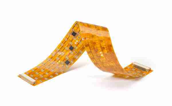
A Flexible PCB is a sort of circuit board planned to flex amid its utilize. Not at all like unbending PCBs made from difficult materials like FR4 (fiberglass epoxy), flex PCBs utilize Flexible base materials such as polyimide or polyester film. These materials permit the circuit to twist and accommodate to different shapes, empowering architects to fit circuits into compact and unpredictable spaces.
The layers of a Flexible PCB include:
- Base substrate (ordinarily polyimide)
- Copper traces
- Adhesive layers
- Coverlay (a Flexible Solder mask)
These layers are reinforced together to shape a lean, bendable, and lightweight circuit that can handle energetic or inactive flexing.

Rigid-Flex PCB | Flexible PCB | FPC | flex-PCB | flexible circuit board | flex-PCB manufacturer | PCB supplier | Rigid-PCB vs Flexible PCB | Circuit Card Assembly
How Do Flexible PCBs Work?
Flexible PCBs work the same way as conventional PCBs: they interface and bolster electronic components through conductive tracks, cushions, and other highlights Automotiveved from copper Boards. In any case, their key contrast lies in their capacity to keep up electrical execution beneath mechanical stress.
When a flex PCB twists, the copper follows stretch or compress. To anticipate breaking or flag debasement, these follows are outlined with particular twist radii and are regularly steered in bends instep of sharp points. Engineers to utilize specialized methods such as “hatched ground planes” to keep up flag keenness whereas lessening mechanical stress.
The adaptability of the board doesn’t influence the electronic signals or usefulness if outlined accurately. Instep, it improves the product’s convenience, especially where development or compactness is basic.
Key Applications of Flexible PCBs
1.Customer Electronics
Flexible PCBs are broadly utilized in smart phones, tablets, wearable electronics, and foldable contraptions. Their capacity to twist permits producers to pack more usefulness into littler designs whereas keeping up execution and durability.
2.Restorative Devices
Flex PCBs are perfect for compact, high-reliability therapeutic gear like hearing helps, pacemakers, symptomatic electronics, and wearable wellbeing screens. Their biocompatibility and capacity to accommodate to the human body make them perfect for negligibly intrusive and implantable technology.
3.Automotive Electronics
Today’s vehicles are prepared with progressed electronics for security, infotainment, and independent highlights. Flexible PCBs are found in dashboard shows, rear-view cameras, Driven lighting, and progressed driver-assistance frameworks (ADAS). Their vibration resistance and toughness beneath temperature vacillations are pivotal for Automotive applications.
4.Aviation and Defense
In aviation, weight decrease is basic. Flex PCBs contribute to lighter flying machine and shuttle frameworks. Their unwavering quality and execution in extraordinary situations make them appropriate for communication frameworks, route controls, and satellites.
5.Mechanical Equipment
Industrial robotization and mechanical autonomy utilize Flexible PCBs to interface moving parts and sensors. These Boards handle the mechanical stretch of monotonous developments whereas guaranteeing dependable flag transmission and control delivery.
Integration of Flexible PCBs in Item Design
Integrating Flexible PCBs into a item is not basically a matter of supplanting a inflexible board with a Flexible one. It includes particular plan, Manufacturing, and Assembly considerations:
1.Plan Considerations
- Bend Span: To anticipate harm, engineers plan the format to maintain a strategic distance from sharp twists. The suggested twist sweep depends on the board’s thickness and number of flex cycles.
- Trace Directing: Conductive follows ought to take after bended ways and maintain a strategic distance from right points to diminish stretch concentration.
- Stiffeners: Inflexible segments may be included to back components and connectors where adaptability is not required.
2.Component Placement
Flex circuits can have surface-mount or through-hole components, but architects must consider arrangement Automotive fully. Components are ordinarily mounted on level, hardened segments to anticipate harm amid bending.
3.Assembly Process
Flexible PCBs require specialized taking handling of amid assembly to maintain a strategic distance from tears or wrinkles. Robotized assembly machines are frequently adjusted to back Flexible substrates, and warm profiles for Soldering must be custom-made to the materials used.
4.Testing and Quality Assurance
Testing Flexible PCBs includes extra steps to guarantee mechanical and electrical unwavering quality. Energetic flex testing, warm cycling, and visual assessment beneath amplification are common practices.
Advantages of Flexible PCBs
- Space and Weight Investment funds: Their lean profile permits for compact designs in tight spaces.
- Dynamic Adaptability: Valuable in items where development is steady, like mechanical arms or foldable phones.
- Improved Unwavering quality: Less connectors and Solder joints decrease the chance of mechanical failure.
- Design Flexibility: They can be formed to fit special geometries, empowering inventive item designs.
Challenges in Utilizing Flexible PCBs
Despite their preferences, flex PCBs too show challenges:
- Higher Taken a toll: Fabric and Manufacturing costs are higher than for inflexible PCBs.
- Complex Plan Rules: Originators must take after strict rules to maintain a strategic distance from disappointments amid bending.
- Specialized Manufacturing: Not all PCB producers are prepared to create flex or rigid-flex Boards, restricting sourcing options.
Conclusion
Designing a Flexible PCB for ideal execution includes a all encompassing approach that envelops electrical, mechanical, and Manufacturing contemplations. By selecting the right materials, keeping up appropriate twist radii, applying savvy format methodologies, and collaborating with producers, originators can create Flexible PCBs that are not as it were useful but too dependable and long-lasting.
Whether you’re building wearable tech, space-bound disobedient, or foldable phones, understanding and applying the standards of Flexible PCB plan will set your item separated in execution and durability.
As request for compact, dependable, and high-performance electronics proceeds to rise, acing Flexible PCB plan is more basic than ever.
Latest Blog


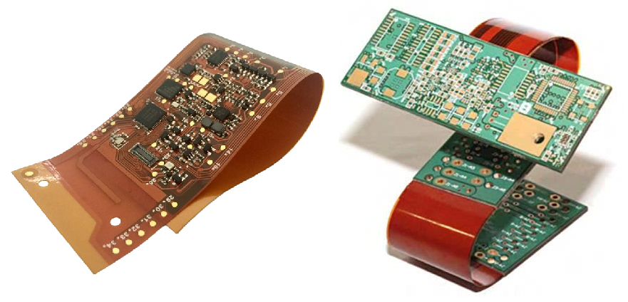

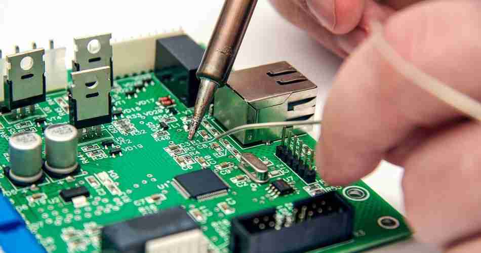

Table of Content
Contcat Us
Phone: +86-18123905375
Email: sales@circuitcardassembly.com
Skype: ali_youte
WhatsApp: +86-18123905375
Wechat: +86-18123905375

 Afrikaans
 Shqip
Shqip አማርኛ
አማርኛ العربية
 Հայերեն
 Azərbaycan dili
 Euskara
 Беларуская мова
 বাংলা
বাংলা Bosanski
 Български
 Català
 Cebuano
 Chichewa
 简体中文
简体中文 繁體中文
繁體中文 Corsu
Corsu Hrvatski
 Čeština
 Dansk
Dansk Nederlands
 Esperanto
 Eesti
Eesti Filipino
 Suomi
Suomi Français
 Frysk
Frysk Galego
 ქართული
 Deutsch
 Ελληνικά
 ગુજરાતી
 Kreyol ayisyen
 Harshen Hausa
 Ōlelo Hawaiʻi
 עִבְרִית
 हिन्दी
 Hmong
Hmong Magyar
 Íslenska
 Igbo
Igbo Bahasa Indonesia
 Gaeilge
 Italiano
 日本語
日本語 Basa Jawa
 ಕನ್ನಡ
ಕನ್ನಡ Қазақ тілі
 ភាសាខ្មែរ
 한국어
한국어 كوردی
كوردی Кыргызча
 ພາສາລາວ
 Latin
Latin Latviešu valoda
 Lietuvių kalba
 Lëtzebuergesch
 Македонски јазик
 Malagasy
 Bahasa Melayu
 മലയാളം
 Maltese
 Te Reo Māori
 मराठी
मराठी Монгол
 ဗမာစာ
ဗမာစာ नेपाली
 Norsk bokmål
 پښتو
پښتو فارسی
فارسی Polski
 Português
 ਪੰਜਾਬੀ
 Română
 Русский
 Samoan
 Gàidhlig
 Српски језик
 Sesotho
 Shona
Shona سنڌي
سنڌي සිංහල
සිංහල Slovenčina
 Slovenščina
 Afsoomaali
 Español
 Basa Sunda
 Kiswahili
 Svenska
 Тоҷикӣ
 தமிழ்
தமிழ் తెలుగు
 ไทย
ไทย Türkçe
 Українська
 اردو
اردو O‘zbekcha
 Tiếng Việt
 Cymraeg
 isiXhosa
 יידיש
יידיש Yorùbá
 Zulu
Zulu